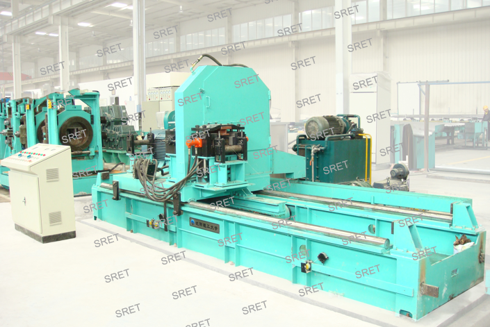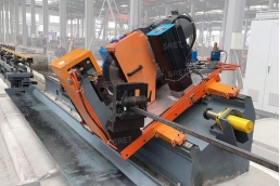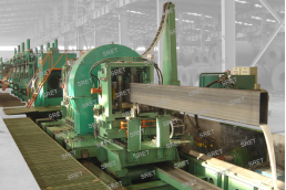


Flying cut off adopts globally advanced motion control computer system, which helps realize to cut the tube, while remaining synchronized speed with tube mill line, precisely at pre-set cut length. Upon the completion of cutting, the computer sends a return command to drive the flying cut off to the initial position.
When the tube from the sizing mill comes to the flying cut off, it runs on a speed measuring roll. A photoelectric encoder installed on it measures and converts the speed and length of the running tube into pulse electronic signals and transmits them into the motion control system. While receiving the instruction signals from the control system, the traveling carriage powered by DC motor and driven via a rack and pinion mechanism, starts accelerating to track the running tube. The carriage reaches the speed of the tube mill line, and then remains synchronization. When the pre-set cut length is reached, the clamping fixtures installed on the carriage clamp the running tube, actuated hydraulically or pneumatically. The high-speed rotating saw blade quickly falls under the control of the cylinder /oil cylinder, relying on the heat generated by the friction between the saw blade and the tube to melt and cut off the metal. Upon the completion of cutting, the clamps open, the travelling carriage instructed by the motion control system quickly decelerates and stops, and all the feeding and sawing systems and travelling carriage return to the original position or status, and wait for the next work cycle.
Flying cut off operates via a reliable numeric motion control system and realize a completely automated on-line cutting. Its work process sequences are: traveling carriage acceleration, synchronous track, clamp, cut off, and quick return to the original position. Once programmed, flying cut off is able to work completely automatically at an unmanned mode. The saw blade can be eight TCT or HSS.
| Model No. | Ø (mm) | Thickness (mm) | Length (m) | Tolerance (mm) | Speed (m/min) | Cut Off Mode |
| FJ19 | 10 – 19 | 0.6 – 1.6 | 4 – 12 | ≤ ±2 | 0 – 140 | Pneumatic |
| FJ32 | 10 – 32 | 0.6 – 1.6 | 4 – 12 | ≤ ±2 | 0 – 140 | Pneumatic |
| FJ50 | 20 – 50 | 1.0 – 3.5 | 4 – 12 | ≤ ±3 | 0 – 130 | Pneumatic |
| FJ76 | 32 – 76 | 1.0 – 4.0 | 4 – 12 | ≤ ±3 | 0 – 110 | Pneumatic |
| FJ89 | 38 – 89 | 1.5 – 4.0 | 4 – 12 | ≤ ±3 | 0 – 100 | Pneumatic |
| FJ114 | 50 – 114 | 1.5 – 5.0 | 4 – 12 | ≤ ±3 | 0 – 80 | Pneumatic |
| FJ165 | 89 – 165 | 2.0 – 7.0 | 4 – 12 | ≤ ±3 | 0 – 75 | Pneumatic / Hydraulic |
| FJ219 | 89 – 219 | 2.0 – 8.0 | 6 – 12 | ≤ ±3 | 0 – 75 | Hydraulic |
| FJ273 | 114 – 273 | 4.0 – 10.0 | 6 – 12 | ≤ ±3 | 0 – 50 | Hydraulic |
| FJ325 | 165 – 325 | 5.0 – 12.0 | 6 – 12 | ≤ ±3 | 0 – 45 | Hydraulic |
| FJ406 | 165 – 406 | 4.0 – 14.0 | 6 – 12 | ≤ ±3 | 0 – 40 | Hydraulic |
| Model No. | Flange (mm) | Web (mm) | Speed (m/min) |
| FJ300 | 200 x 8 | 300 x 5 | 0 – 50 |
| FJ400 | 250 x 12 | 400 x 8 | 0 – 45 |
| FJ500 | 300 x 12 | 500 x 8 | 0 – 40 |
| FJ600 | 300 x 14 | 600 x 10 | 0 – 35 |
| FJ700 | 400 x 16 | 700 x 12 | 0 – 35 |


